Home
› Led Vu Meter Circuit Diagram With Pcb Layout - vu meter using a lm3915 circuit diagram under Repository-circuits -33859- : Next.gr / Circuit diagram and working explanation:
Led Vu Meter Circuit Diagram With Pcb Layout - vu meter using a lm3915 circuit diagram under Repository-circuits -33859- : Next.gr / Circuit diagram and working explanation:
Led Vu Meter Circuit Diagram With Pcb Layout - vu meter using a lm3915 circuit diagram under Repository-circuits -33859- : Next.gr / Circuit diagram and working explanation:. You can use various types of leds (round or square) to get the visual and aesthetic result you want. Meter circuits vu meter schematic using 78l05, ad8313, lm324. The circuit of a simple led vu meter explained here uses the outstanding chip lm3915 from texas instruments. Volume level meter with 8 leds. Vu meter circuit stereo 20 led with pcb eleccircuit com.
Meter circuits vu meter schematic using 78l05, ad8313, lm324. The extra diode (d3) is included to ensure that. 6 led vu meter using one transistor circuit electronics area. I did a toner transfer to make the pcb of my first prototype. 60 db led vu meter schematic circuit diagram.
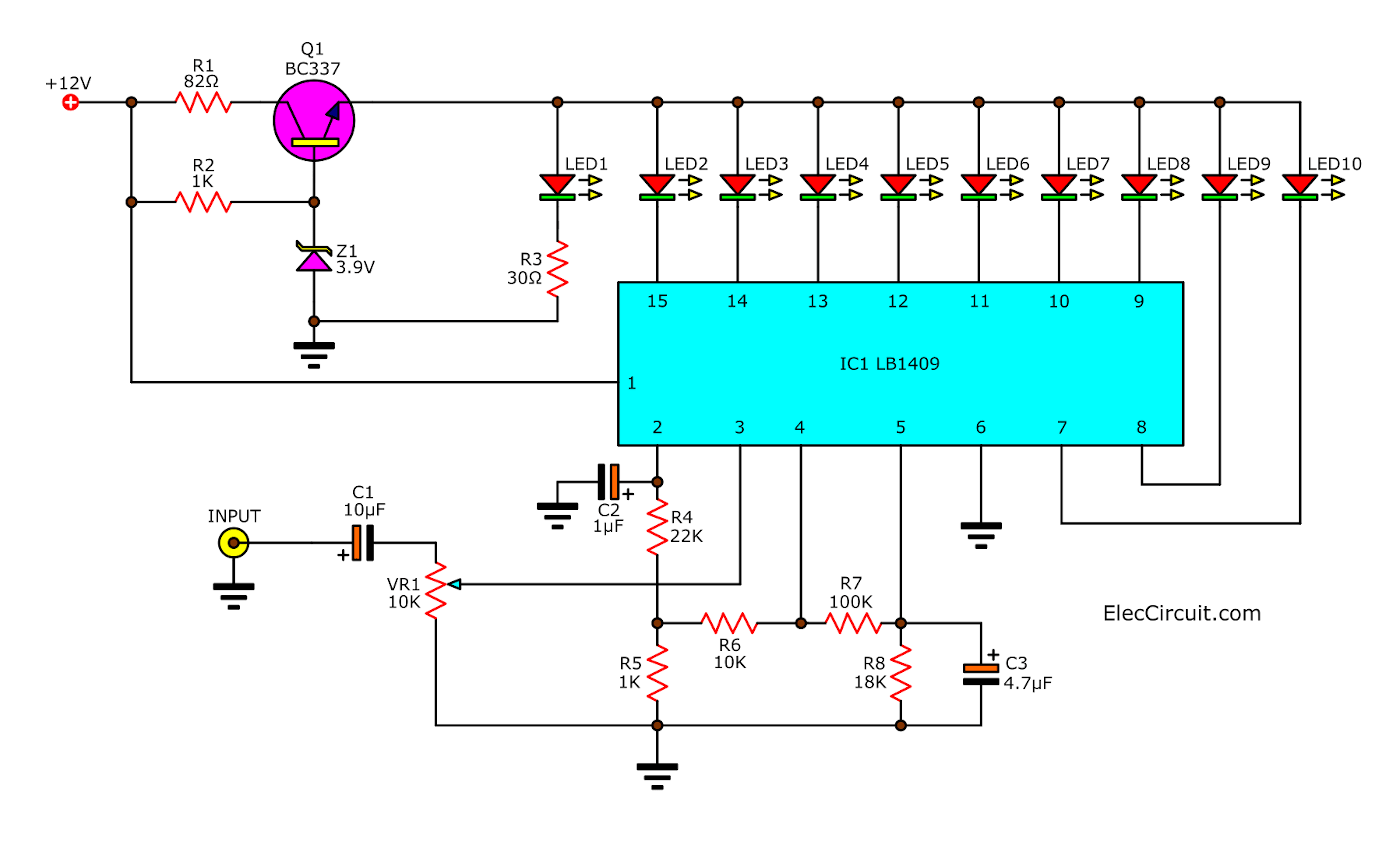
Sound level meter circuit using LB1409 - ElecCircuit.com from www.eleccircuit.com Circuit provides very accurate reading. I did a toner transfer to make the pcb of my first prototype. The switch s1 will allow you to choose whether vu meter will work as a bar or one by. Audio level vu meter by lm3915 ic today i will show you how to make audio level indicator vu meter circuit using lm3915 ic. You can use various types of leds (round or square) to get the visual and aesthetic result you want. You can use various types of leds (round or square) to get the visual and aesthetic result you want. The switch s1 will allow you to choose whether vu meter will work as a bar or one by one (dot). The schematic needs bipolar power supply to work correctly, but the negative rail can be.
Led vu meter.rar use them on your own responsibility!
The circuit diagram of the vu meter is show in below figure hello! Circuit provides very accurate reading. Jlcpcb prototype for $2(any color): Here is my newly developed load cell amplifier circuit. Online shop mcu adjustable display pattern led vu meter level. Does anyone here have a schematic for the prototype of this circuit on proteus ? Volume level meter with 8 leds. Circuit diagram and working explanation: Each of the eight comparators is biased at increasing voltages set by the voltage divider so that the lower right. The top countries of suppliers are. I saw in youtube an interesting commercial led vu meter, which imitates the needle movement in analog vu meters and i thought i can make a similar one. The circuit of a simple led vu meter explained here uses the outstanding chip lm3915 from texas instruments. Led vu meter display sangat membantu 27 best vu metre images electronics projects circuit diagram.
The progression of the illumination of the leds is linear, it is not logarithmic. I need to complete this project on a pcb and need a schematic. Circuit provides very accurate reading. These narrow sections of the ground plane can cause. I changed the value of the resistors that are connected to the series with the leds to 820e to reduce brightness.
Lm3915 Vu Meter - PCB Circuits from i.ytimg.com The switch s1 will allow you to choose whether vu meter will work as a bar or one by one (dot). Sound level meter circuit using lb1409 eleccircuit com. I saw in youtube an interesting commercial led vu meter, which imitates the needle movement in analog vu meters and i thought i can make a similar one. These narrow sections of the ground plane can cause. Below is the snapshot of top layer of pcb layout from easyeda you can view any layer top bottom. This electronic vu meter set is a circuit that high performance and widely popular than 40 years. Circuit diagram and working explanation: Getting continuity on my gssl pcb layout disagrees gearslutz.
The interesting thing about this circuit is that it uses a single transistor as an active component and its operation affects the behavior of the entire circuit.
On a side note do you have suggestions for hobbyist level circuit design software with pcb layout capability? Sound level meter circuit using lb1409 eleccircuit com. The switch s1 will allow you to choose whether vu meter will work as a bar or one by one (dot). The led vu meter circuit uses two lm339 quad voltage comparators to illuminate a series of 8 leds (light emitting diodes) indicating volume level. Circuit diagram and working explanation: Getting continuity on my gssl pcb layout disagrees gearslutz. Led vu meter sometimes called led vu. Vu meter circuit stereomono 20 led with pcb. Led vu meter.rar use them on your own responsibility! 6 led vu meter using one transistor circuit electronics area. 120 led stereo vu meter circuit 120 led ka2281 vu metre devresi sprint layout pcb, gerber download circuit diagram download: Vu meter led , simple circuits using transistors , simple electronics circuits , audio amplifier circuit diagram using transistor , vu meter circuit , audio phase meter , audio level indicator circuit diagram , vu. Of course leds can be soldered directly on the pcb.
The switch s1 will allow you to choose whether vu meter will work as a bar or one by one (dot). This circuit is based on lm3915 ic and uses the logarithmic version. Online shop mcu adjustable display pattern led vu meter level. How does the 6 led vu meter using a transistor works? 6 led vu meter using one transistor circuit electronics area.
Peak Hold VU meter circuit- ElecCircuit.com from www.eleccircuit.com You can use various types of leds (round or square) to get the visual and aesthetic result you want. This electronic vu meter set is a circuit that high performance and widely popular than 40 years. The top countries of suppliers are. 60 db led vu meter schematic circuit diagram. Skema rangkaian led vu display pcb blogkamarku com. The switch s1 will allow you to choose whether vu meter will work as a bar or one by. You can use various types of leds (round or square) to get the visual and aesthetic result you want. The switch s1 will allow you to choose whether vu meter will work as a bar or one by one (dot).
The interesting thing about this circuit is that it uses a single transistor as an active component and its operation affects the behavior of the entire circuit.
Led audio vu level meter using transistors. Audio level vu meter by lm3915 ic today i will show you how to make audio level indicator vu meter circuit using lm3915 ic. Getting continuity on my gssl pcb layout disagrees gearslutz. But the pcb layout is okay. Meter circuits vu meter schematic using 78l05, ad8313, lm324. The led vu meter circuit uses two lm339 quad voltage comparators to illuminate a series of 8 leds (light emitting diodes) indicating volume level. Circuit provides very accurate reading. Vu meter circuit diagram ic b1403: The switch s1 will allow you to choose whether vu meter will work as a bar or one by. I saw in youtube an interesting commercial led vu meter, which imitates the needle movement in analog vu meters and i thought i can make a similar one. Vu meter circuit stereo 20 led with pcb eleccircuit com. Led vu meter sometimes called led vu. My experiment 40 levels vu meter led or led vu display without ic (integrated circuit) yıl önce.