Home
› Pid Temperature Controller Wiring Diagram - MyPin TD4-SNR with PT100 Wiring Diagram - Home Brew Forums - Available configurations caution this controller is intended to control equipment under normal operating table 1.
Pid Temperature Controller Wiring Diagram - MyPin TD4-SNR with PT100 Wiring Diagram - Home Brew Forums - Available configurations caution this controller is intended to control equipment under normal operating table 1.
Pid Temperature Controller Wiring Diagram - MyPin TD4-SNR with PT100 Wiring Diagram - Home Brew Forums - Available configurations caution this controller is intended to control equipment under normal operating table 1.. Start date dec 22, 2010; Collection of temperature controller wiring diagram. That pid will be run by any voltage input between 85vac and 265vac, so just connect it to the 240 vac line. To get book file pdf td4 snr ssr controller wiring diagram. All prices as of june 2011.
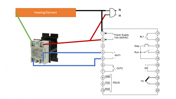
Available configurations caution this controller is intended to control equipment under normal operating table 1. Wire the controller per the appropriate wiring diagram listed on page 6. Temperature controller for actuators with a continuous or pulsed input signal. So, to recap, i have wired the ssr in place of the old thermostat. It reveals the components of the circuit as streamlined shapes, and the power and also signal connections in between the devices.
PID Temperature Controller, Dual Digital, Universal Input | ATO.com from www.ato.com They are traditionally placed in the front panel with the display for easy operator accessibility. Collection of pid temperature controller wiring diagram. So, to recap, i have wired the ssr in place of the old thermostat. To get book file pdf td4 snr ssr controller wiring diagram. For typical wiring diagrams, refer to figures 4, 5 and 6. All prices as of june 2011. 2.4 atvl=auto tuning offset,and it will be deduced from sv Collection of temperature controller wiring diagram.
To get book file pdf td4 snr ssr controller wiring diagram.
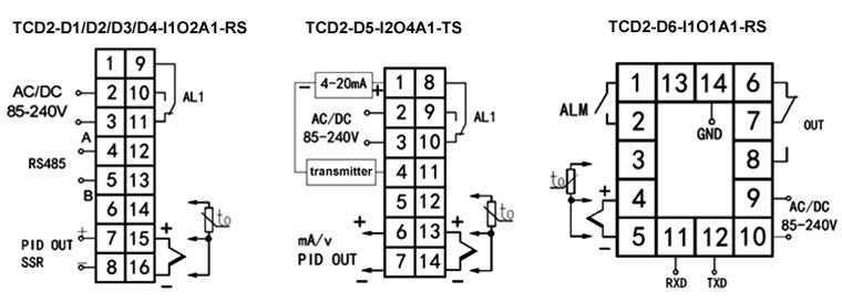
2.3 after auto tuningisfinished,a new set of pid parameter is generated internally to replace the existing pid parameter. A wiring diagram is a simplified standard photographic representation of an electric circuit. A wiring diagram is a simplified traditional pictorial representation of an electrical circuit. Start date dec 22, 2010; Initially i just want a very basic setup. Controlled temperature to setpoint after the system stabilizes. Wiring diagram with thermocouple input on the left and rtd input on the right 3.1 sensor connection 3.1.1 thermocouple the thermocouple should be connected to terminals 6 and 7. They will control a solenoid or a fan, but not a heating coil. If you are using a 3 wire sensor then it connects to terminals 3 4 and 5. April 25, 2020 by larry a. Wire the controller per the appropriate wiring diagram listed on page 6. 4) derivative, also known as rate, senses the rate of rise or fall of system temperature and automatically adjusts the proportional band to minimize overshoot or undershoot. It reveals the components of the circuit as streamlined shapes, and the power and also signal connections in between the devices.
If you are using a 3 wire sensor then it connects to terminals 3 4 and 5. That is a must at the current usage of a kiln. For typical wiring diagrams, refer to figures 4, 5 and 6. Then note the schematic in this label which is from an actual photo of a ta4 pid controller. It reveals the components of the circuit as streamlined shapes, and the power and also signal connections in between the devices.
Need help understanding the MyPin TA4 temperature controller. : AskElectronics from cavemanketo.com A wiring diagram is a simplified standard photographic representation of an electric circuit. Terminal wiring (back view) 678910. Collection of pid temperature controller wiring diagram. Panel cutout dimensions cn730 cn710. It reveals the elements of the circuit as streamlined forms, and also the power and also signal links between the tools. Digital temperature controller circuit and working fig. Wellborn collection of pid temperature controller wiring diagram. It will be a single kettle that i will use as both my hlt and bk.
For typical wiring diagrams, refer to figures 4, 5 and 6.
It reveals the components of the circuit as streamlined shapes, and the power and also signal connections in between the devices. The control mode, the pid parameters can be accessed in the regulation To get book file pdf td4 snr ssr controller wiring diagram. Pm controllers are highly scalable, you only pay for what you need. Start date dec 22, 2010; I have used some regular mains cord to make the extra connections because i plan to put thermal insulation in to protect the pid and the wiring. However, it's not instantly clear what to do with the ssr and how and where to power everything. That pid will be run by any voltage input between 85vac and 265vac, so just connect it to the 240 vac line. The pid controller looks at the setpoint and compares it with the actual value of the process variable (pv). Be sure the ambient temperature is within the stated working range in the manual, especially when there are two or more temperature controllers installed. It will be a single kettle that i will use as both my hlt and bk. A wiring diagram is a simplified standard photographic representation of an electric circuit. All prices as of june 2011.
However, it's not instantly clear what to do with the ssr and how and where to power everything. Available configurations caution this controller is intended to control equipment under normal operating table 1. They will control a solenoid or a fan, but not a heating coil. It reveals the components of the circuit as streamlined shapes, and the power and also signal connections in between the devices. Wiring diagram with thermocouple input on the left and rtd input on the right 3.1 sensor connection 3.1.1 thermocouple the thermocouple should be connected to terminals 6 and 7.
Pid Temperature Controller Wiring Diagram from www.mikrora.com 4) derivative, also known as rate, senses the rate of rise or fall of system temperature and automatically adjusts the proportional band to minimize overshoot or undershoot. However, it's not instantly clear what to do with the ssr and how and where to power everything. Pm controllers are highly scalable, you only pay for what you need. Back in our house, the box of electronics that is the pid controller in our heating and cooling system looks at the value of the temperature sensor in the room and sees how close it is to 22°c. Start date dec 22, 2010; All prices as of june 2011. Hopefully my digram below will make things a little clearer. For typical wiring diagrams, refer to figures 4, 5 and 6.
* auto tuning allows the controller to automatically adjust the pid parameter, and is suitable for use when temperature control is not accurate enough.
A wiring diagram is a simplified traditional pictorial representation of an electrical circuit. It reveals the elements of the circuit as streamlined forms, and also the power and also signal links between the tools. Wiring diagram with thermocouple input on the left and rtd input on the right 3.1 sensor connection 3.1.1 thermocouple the thermocouple should be connected to terminals 6 and 7. A wiring diagram is a simplified standard photographic representation of an electric circuit. Temperature controller for actuators with a continuous or pulsed input signal. The control mode, the pid parameters can be accessed in the regulation It shows the components of the circuit as simplified shapes, and the skill and signal contacts in the midst of the devices. Mypin ta4 snr controller for uds. Is no gap among the controller, panel and the adapter and then fasten the two screws on the adapter with the torque of 0.29n to 0.39n. Wellborn collection of pid temperature controller wiring diagram. Pm controllers are highly scalable, you only pay for what you need. Digital temperature controller circuit and working fig. 4) derivative, also known as rate, senses the rate of rise or fall of system temperature and automatically adjusts the proportional band to minimize overshoot or undershoot.