Charger Pcb Diagram - Pcb Layout Battery Charger Pcb Circuits - How does a lead acid battery charger work?. For calibrating the circuit, you need a variable dc power supply (a bench power supply). Find pcb printed circuit board. Try this circuit at your own risk. Connect a lead acid battery at the battery side (as per the circuit.) Automatic charger circuit for any battery auto cut off battery.
The design is quite straight forward, built on a paper phenolic pcb, could be easily repaired. The voltage regulator used here is 7815, which is a 15v regulator. Lead acid batteries are one of the oldest rechargeable batteries available today. Connect a lead acid battery at the battery side (as per the circuit.) Take all the necessary precautions as you might be handling mains voltage and high potential dc.
12v 24v Automatic Mobile Battery Charger Pcb Circuit Diagram Buy Mobile Battery Charger Circuit Diagram 12v 24v Automatic Battery Charger Pcb Pcb Circuit Diagram Product On Alibaba Com from sc04.alicdn.com Now disconnect the power supply and connect the jumper between 1 and 2. 7 4v two step lithium battery charger circuit cc and cv mode 9. The main concern with any battery is it discharges over time and must be recharged so that it can provide the necessary voltage and current. There is also a trickle charge mode circuitry which will help to reduce the current when the battery is fully charged. Your circuit is ready as all you need is a dc (or ac) supply of 18v. Initially, set the jumper between positions 2 and 3 for calibrating. Pcbbuy faster response times better understandings of your pcb needs. Before seeing the working, let me show you how to calibrate the circuit.
Take all the necessary precautions as you might be handling mains voltage and high potential dc.
Most popular pcb manufacturer, 800,000+ customers worldwide use jlc service. See full list on electronicshub.org Before seeing the working, let me show you how to calibrate the circuit. Apr 06, 2018 · unfortunately every charger circuit is not same, some of them contains few extra capacitors or resistors. More images for charger pcb diagram » Is the mobile charger circuit the same as the pcb? Jan 23, 2020 · the following diagram shows how the ic lm324 may be wired up as a 4 step battery voltage monitor and cut off circuit. There is also a trickle charge mode circuitry which will help to reduce the current when the battery is fully charged. Sep 22, 2016 · the circuit diagram of 12v, 7ah smart battery charger is shown in figure 1. Warning:before proceeding further, i want you to know that this circuit is tested in a specific test conditions and we do not guarantee that it will be 100% successful. Different batteries have different strategies of charging and in this project, i will show you how to recharge a lead acid battery using a simple lead acid battery charger circuit. Part list of the mobile charger circuit Take all the necessary precautions as you might be handling mains voltage and high potential dc.
Automatic charger circuit for any battery auto cut off battery. See full list on electronicshub.org Most popular pcb manufacturer, 800,000+ customers worldwide use jlc service. The 14.5v we set in the calibration is called the tripping point. See full list on electronicshub.org
How To Make Automatic 12v Lead Acid Battery Charger Circuit Board Youtube from i.ytimg.com Try this circuit at your own risk. Please take proper safety precaution while working with 220v or 110v supply. The voltage regulator used here is 7815, which is a 15v regulator. Most popular pcb manufacturer, 800,000+ customers worldwide use jlc service. Jan 23, 2020 · the following diagram shows how the ic lm324 may be wired up as a 4 step battery voltage monitor and cut off circuit. For calibrating the circuit, you need a variable dc power supply (a bench power supply). There is also a trickle charge mode circuitry which will help to reduce the current when the battery is fully charged. See full list on electronicshub.org
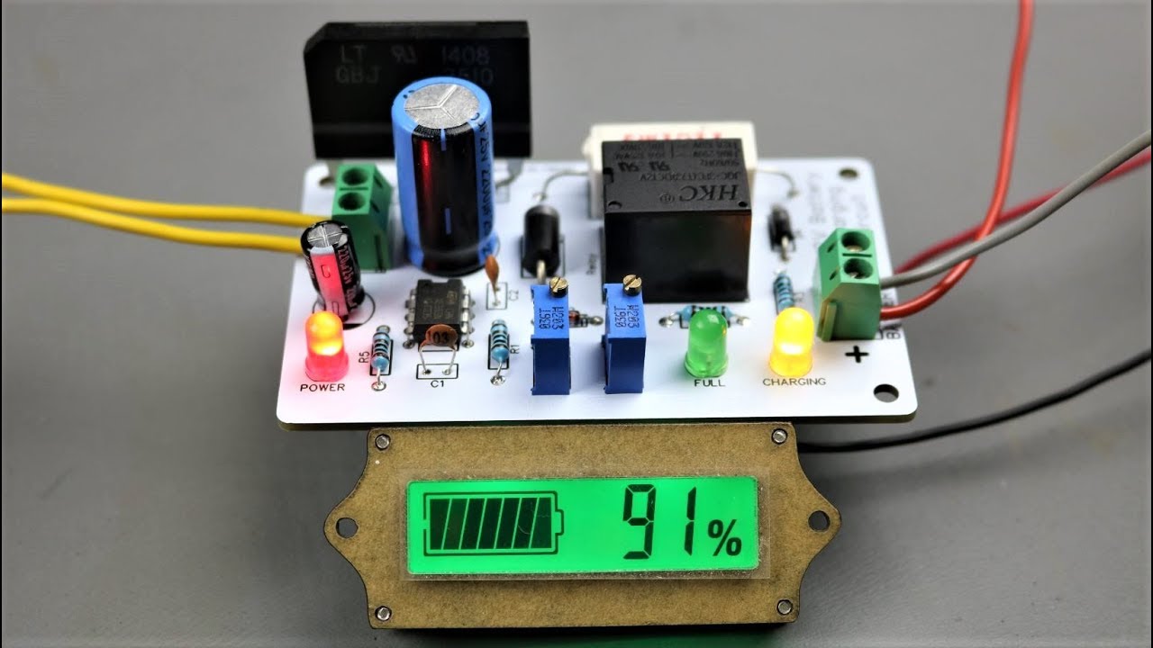
Circuit diagram please connect an led in series with r1, r2, r3, r4, each in order to get a synchronous reading of the charging status of the battery.
Pcbbuy faster response times better understandings of your pcb needs. But even though, you can get a clear overview of the mobile charger circuit from the above diagram. For calibrating the circuit, you need a variable dc power supply (a bench power supply). Pcbbuy faster response times better understandings of your pcb needs. 7 4v two step lithium battery charger circuit cc and cv mode 9. Most popular pcb manufacturer, 800,000+ customers worldwide use jlc service. Battery charger for 12v sla project electronic circuit diagrams. See full list on electronicshub.org Try this circuit at your own risk. Initially, set the jumper between positions 2 and 3 for calibrating. Most popular pcb manufacturer, 800,000+ customers worldwide use jlc service. Circuit diagram please connect an led in series with r1, r2, r3, r4, each in order to get a synchronous reading of the charging status of the battery. More images for charger pcb diagram »
Take all the necessary precautions as you might be handling mains voltage and high potential dc. Now slowly turn the 50kω potentiometer until the "charged" led turns on. Circuit diagram please connect an led in series with r1, r2, r3, r4, each in order to get a synchronous reading of the charging status of the battery. Due to their low cost (for the capacity) compared to newer battery technologies and the ability to provide high surge currents (an important factor in automobiles), lead acid batteries are still the preferred choice of batteries in almost all vehicles. See full list on electronicshub.org
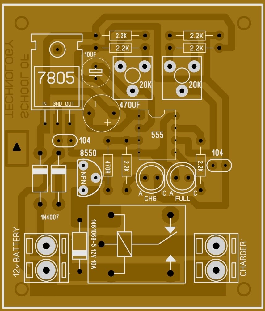
12v 100ah Automatic Battery Charge Control Circuit Soldering Mind from solderingmind.com When the tripping point is set to 14.5v, the battery will charge for about 75% of its capacity. See full list on electronicshub.org Most popular pcb manufacturer, 800,000+ customers worldwide use jlc service. As seen in the above block diagram, a dc voltage is given to the dc voltage regulator. 12 volt 10 amp transformer battery charger circuit diagram.for more information visit our site: Jan 23, 2020 · the following diagram shows how the ic lm324 may be wired up as a 4 step battery voltage monitor and cut off circuit. Your circuit is ready as all you need is a dc (or ac) supply of 18v. Circuit diagram please connect an led in series with r1, r2, r3, r4, each in order to get a synchronous reading of the charging status of the battery.
Is there an auto charger circuit for a 12v battery?
Find pcb printed circuit board. What to look for in a mobile charger circuit diagram? The voltage regulator used here is 7815, which is a 15v regulator. How does a lead acid battery charger work? If you want to charge 100%, then set the tripping point to ≈16v by removing the 7815 regulator and directly supplying 18v dc, but this is not recommended. Your circuit is ready as all you need is a dc (or ac) supply of 18v. Battery charger for 12v sla project electronic circuit diagrams. But even though, you can get a clear overview of the mobile charger circuit from the above diagram. Please take proper safety precaution while working with 220v or 110v supply. Initially, set the jumper between positions 2 and 3 for calibrating. Then we can give the regulated voltage to the battery to charge it. Try this circuit at your own risk. Lead acid batteries are one of the oldest rechargeable batteries available today.