Home
› Wiring Outlets Diagram - Wiring Diagrams for Electrical Receptacle Outlets - Do-it-yourself-help.com / The long slot on the left is the neutral contact and the short slot is the hot contact.
Wiring Outlets Diagram - Wiring Diagrams for Electrical Receptacle Outlets - Do-it-yourself-help.com / The long slot on the left is the neutral contact and the short slot is the hot contact.
Wiring Outlets Diagram - Wiring Diagrams for Electrical Receptacle Outlets - Do-it-yourself-help.com / The long slot on the left is the neutral contact and the short slot is the hot contact.. Insert the new outlet into the electrical. Wiring 2 outlets with 2 sources in this diagram, two outlets are wired in the same box with a separate 120 volt source feeding each. At the outlets, each is wired using a pigtail splice to make the hot and neutral connections. Wiring a receptacle (also referred to as an outlet) is another of those fundamental wiring skills that every diyer should feel comfortable undertaking. The tab between the neutral, silver terminals should remain intact.
Wiring a new 220 outlet is a project that someone who has experience working with electricity can do safely by working carefully and following the proper precautions. Of sheathing off the wires and thread the wires and about 1/2 in. Wiring diagram for multiple outlets this diagram shows the wiring for multiple receptacles in an arrangement that connects each individually to the source. Insert the new outlet into the electrical. In this gfci outlet wiring and installation diagram, the combo (switch + outlet), spst (single way) switch and ordinary outlet is connected to the load side of gfci.
How To Wire An Electrical Outlet Wiring Diagram | House Electrical Wiring Diagram from 3.bp.blogspot.com And second, it's easier to press the outlet back into the box if fewer of its screws are connected to wires. Multiple outlet in serie wiring diagram : It means, all the connected loads to the load terminals of gfci are protected. For wiring in series, the terminal screws are the means for passing voltage from one receptacle to another. Switched outlet wiring diagram depicts the electrical power from the circuit breaker panel entering the switched electrical receptacle outlet box where a two wire cable goes to the switch and another two wire cable feeds power to another outlet that is live at all times. This article and detailed wiring diagram explains the steps to wiring the common household receptacle/outlet. This repeats until the end of the chain. Wiring electrical outlets (properly called receptacles) and switches involve many of the same basic techniques.
It means, all the connected loads to the load terminals of gfci are protected.
First, connecting the wires leading to downstream outlets with wire connectors creates a more secure connection. This article and detailed wiring diagram explains the steps to wiring the common household receptacle/outlet. At the outlets, each is wired using a pigtail splice to make the hot and neutral connections. The black and red wires are both hot and each is connected to one of the receptacles. Understanding switched outlet wiring for home electrical applications the switched outlet wiring configurations show two different wiring scenarios which are most commonly used. Begin by planning your wiring scheme and nailing up all the electrical boxes. The toggle switch in the combo switch outlet controls the first light bulb while the single way. The black wire (line) and white (neutral) connect to the receptacle terminals and another 2 wire nm that travels to the next receptacle. The 15a, 125v receptacle is the most widely used device in your home. The above wiring circuit was made using only a two conductor cable with ground. And second, it's easier to press the outlet back into the box if fewer of its screws are connected to wires. Wiring diagram for multiple switched outlets. As shown in the fig, the switch is firstly installed in the wiring the hot wire from switch feeds all the other parallel connected outlets hence, the outlet on/off operation can be controlled through the switch.
At the outlets, each is wired using a pigtail splice to make the hot and neutral connections. The above wiring circuit was made using only a two conductor cable with ground. Wiring electrical outlets (properly called receptacles) and switches involve many of the same basic techniques. This is a polarized device. To run a cable from one box to another, pull cable off the coil, strip at least 8 in.
Leviton Presents: How To Install A Combination Device With A Single - Light Switch Outlet Combo ... from 2020cadillac.com The 15a, 125v receptacle is the most widely used device in your home. As shown in the fig, the switch is firstly installed in the wiring the hot wire from switch feeds all the other parallel connected outlets hence, the outlet on/off operation can be controlled through the switch. In this case, the circuit load flows both to the receptacle and to any downstream receptacles without being dependent on flowing through the receptacle's connecting tab. To run a cable from one box to another, pull cable off the coil, strip at least 8 in. This is a polarized device. The tab between the neutral, silver terminals should remain intact. Begin by planning your wiring scheme and nailing up all the electrical boxes. With this arrangement, all the outlets will turn on and off at the same time.
As shown in the fig, the switch is firstly installed in the wiring the hot wire from switch feeds all the other parallel connected outlets hence, the outlet on/off operation can be controlled through the switch.
Alternate split receptacle wiring diagram. The wiring diagram above shows how switched outlets are often wired. Of sheathing through the wire opening in the box. It means, all the connected loads to the load terminals of gfci are protected. Duplex receptacle outlets are made for feed through of the power from one receptacle to the next. These outlets are not switched. Understanding switched outlet wiring for home electrical applications the switched outlet wiring configurations show two different wiring scenarios which are most commonly used. The video covers how to strip electrical wire, create loops on the load, neutral, and ground wire, and how to. In the first outlet box strip ½ inch of the insulation off the ends of the wire you've just run. To run a cable from one box to another, pull cable off the coil, strip at least 8 in. The 15a, 125v receptacle is the most widely used device in your home. Begin by planning your wiring scheme and nailing up all the electrical boxes. Wiring electrical outlets (properly called receptacles) and switches involve many of the same basic techniques.
As shown in the fig, the switch is firstly installed in the wiring the hot wire from switch feeds all the other parallel connected outlets hence, the outlet on/off operation can be controlled through the switch. The black wire (line) and white (neutral) connect to the receptacle terminals and another 2 wire nm that travels to the next receptacle. Wiring diagram for multiple switched outlets. This is a polarized device. Wiring a receptacle (also referred to as an outlet) is another of those fundamental wiring skills that every diyer should feel comfortable undertaking.
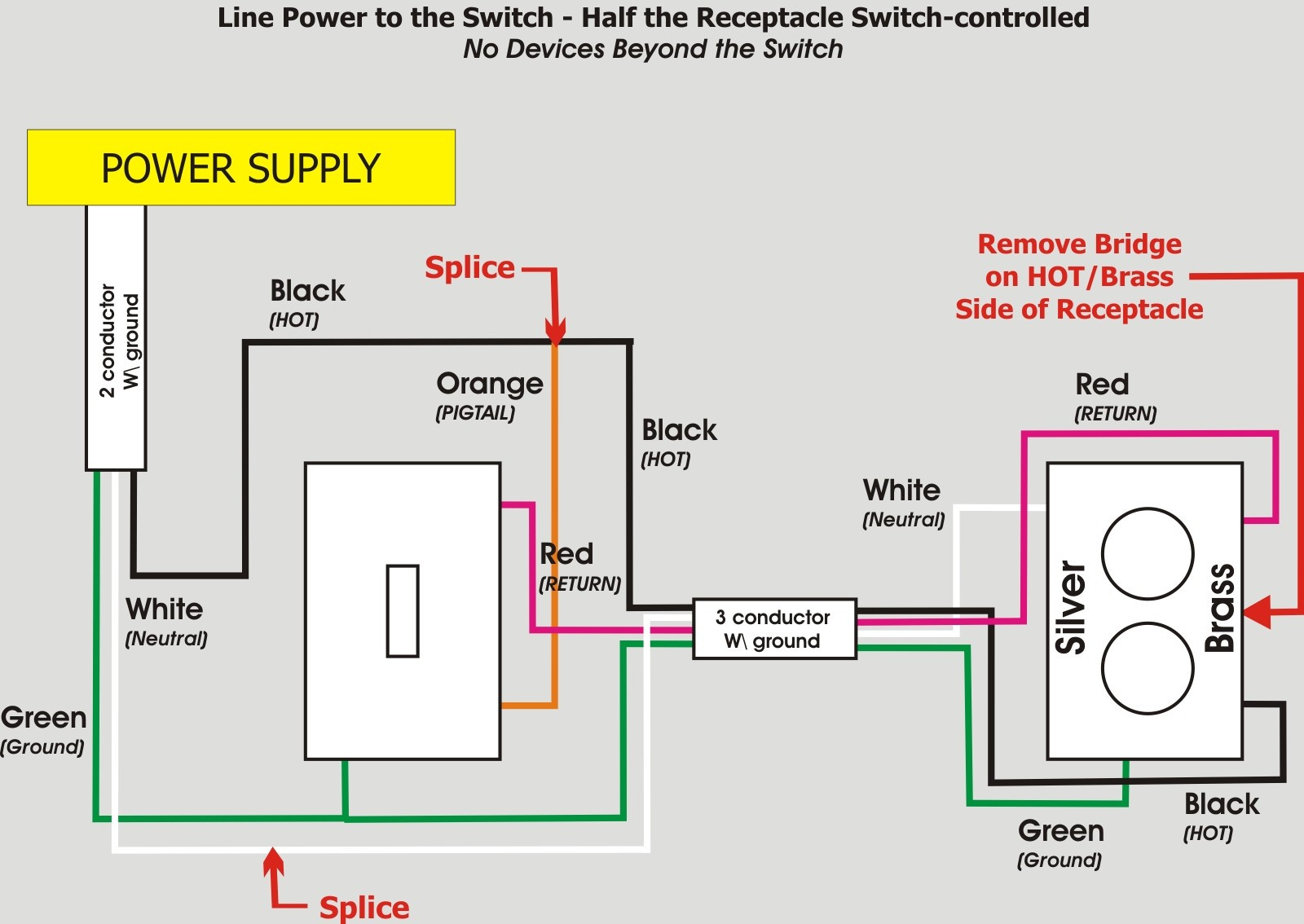
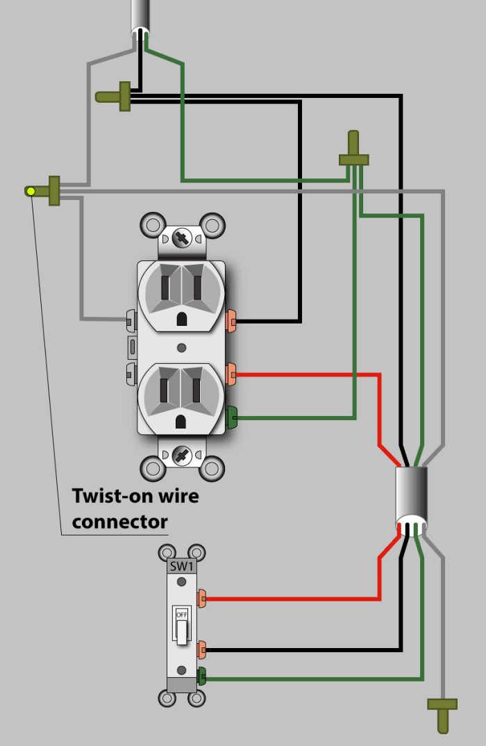
An Electrician Explains How to Wire a Switched (Half-Hot) Outlet - Dengarden - Home and Garden from images.saymedia-content.com With this arrangement, all the outlets will turn on and off at the same time. The video covers how to strip electrical wire, create loops on the load, neutral, and ground wire, and how to. The black wire (line) and white (neutral) connect to the receptacle terminals and another 2 wire nm that travels to the next receptacle. These outlets are not switched. A grounded contact at the bottom, center is crescent shaped. Wiring 2 outlets with 2 sources in this diagram, two outlets are wired in the same box with a separate 120 volt source feeding each. All wires are spliced to a pigtail which is connected to each device separate from all the others in the row. First, connecting the wires leading to downstream outlets with wire connectors creates a more secure connection.
And second, it's easier to press the outlet back into the box if fewer of its screws are connected to wires.
Begin by planning your wiring scheme and nailing up all the electrical boxes. With this arrangement, all the outlets will turn on and off at the same time. The 15a, 125v receptacle is the most widely used device in your home. As shown in the fig, the switch is firstly installed in the wiring the hot wire from switch feeds all the other parallel connected outlets hence, the outlet on/off operation can be controlled through the switch. Multiple outlet in serie wiring diagram : Wiring diagram for multiple outlets this diagram shows the wiring for multiple receptacles in an arrangement that connects each individually to the source. Wiring 2 outlets with 2 sources in this diagram, two outlets are wired in the same box with a separate 120 volt source feeding each. The long slot on the left is the neutral contact and the short slot is the hot contact. This switched outlet electrical wiring diagram shows two scenarios of wiring for a typical half hot outlet that can be used to control a table or floor lamp. These outlets are not switched. The video covers how to strip electrical wire, create loops on the load, neutral, and ground wire, and how to. Wiring electrical outlets (properly called receptacles) and switches involve many of the same basic techniques. However, working on your circuit breaker box and electrical system can lead to serious injury or death if you don't know what you're doing, so hire an electrician if you don.