Home
› 3 Position Switch Wiring Diagram : Diagram 1951 Farmall M Wiring Diagram Full Version Hd Quality Wiring Diagram Milsdiagram Viafrankcesena It : Yourproducthere.co variety of 3 position toggle switch wiring diagram.
3 Position Switch Wiring Diagram : Diagram 1951 Farmall M Wiring Diagram Full Version Hd Quality Wiring Diagram Milsdiagram Viafrankcesena It : Yourproducthere.co variety of 3 position toggle switch wiring diagram.
3 Position Switch Wiring Diagram : Diagram 1951 Farmall M Wiring Diagram Full Version Hd Quality Wiring Diagram Milsdiagram Viafrankcesena It : Yourproducthere.co variety of 3 position toggle switch wiring diagram.. 3.1 system structure and wiring. Even though these switches have 3 positions, they are still considered double throw because another 'throw' implies a connection to yet another terminal wiring the phase switch is fairly simple. 819 3 position switch wiring diagram products are offered for sale by suppliers on alibaba.com, of which rocker switches accounts for 1%, push there are 22 suppliers who sells 3 position switch wiring diagram on alibaba.com, mainly located in asia. Pmt sonic expansion control diagrams. A spst switch only has one throw, but has two positions.
Three position dpdt switch wiring diagram pdf epub ebook. How to test which wire is which speed? A wiring diagram is a visual representation of components and wires related to an electrical connection. The diagram below will give you a better understanding how this circuit is wired. Signal (zps) 12 negation signal for internal position control & internal speed control (cmdinv) 13 instruction division/ multiplication switch 0 (div0) 14 instruction 41.
3 Way Rotary Lamp Switch Wiring Diagram Wiring Diagram Networks from png2.kisspng.com There are no connections between the three gangs in fig 2 intermediate switch related circuit diagrams and wiring diagrams intermediate switch wiring diagram (old cable colours) intermediate switch wiring. 16 position rotary switch wiring diagram kraus amp naimer ltd nz, ac rotary switch off 3 positions 120v ac 30a blue, assistance wiring a 3 speed box fan rotary. Click on the image to enlarge, and then save it to your computer by. Don't disconnect old switch before you are certain about the wiring. Basic circuit function carlingtech com. Yourproducthere.co variety of 3 position toggle switch wiring diagram. Repair guides wiring diagrams wiring diagrams autozone com. 3.1 system structure and wiring.
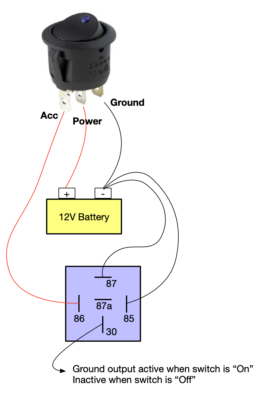
In position 2 (when the switch is up or 'off'), com and l2 are connected together.
3.1 system structure and wiring. Three position dpdt switch wiring diagram pdf epub ebook. F electrical wiring diagram (system circuits). Rotary drum switch wiring diagram salzer drum switch switches. 11 wiring diagrams and trouble diagnosis. This diagram is a thumbnail. Basic circuit function carlingtech com. Custom drawn guitar wiring diagrams. See more ideas about 3 way switch wiring, home electrical wiring, diy electrical. Pmt sonic expansion control diagrams. Here are a few that may be of interest. How to test which wire is which speed? Pnp switch throttle position sensor closed throttle position switch wide open throttle position switch engine speed signal a/t fluid temperature sensor revolution sensor vehicle speed sensor overdrive control switch ascd control unit stop.
Matt looks at the basic wiring diagram for a circuit controlled by a passive infrared sensor (pir) switching a contactor controlling a load). 16 position rotary switch wiring diagram kraus amp naimer ltd nz, ac rotary switch off 3 positions 120v ac 30a blue, assistance wiring a 3 speed box fan rotary. Throttle position sensor accelerator pedal position sensor idle speed control servo windshield wiper motor dual pressure switch. Automatic transfer switch (open transition) at. Basic circuit function carlingtech com.
On Off Switch Led Rocker Switch Wiring Diagrams Oznium from e6960098ef1617903b5d-a80c747d8d9df12f4e1ef66b12f9c948.ssl.cf1.rackcdn.com Repair guides wiring diagrams wiring diagrams autozone com. Matt looks at the basic wiring diagram for a circuit controlled by a passive infrared sensor (pir) switching a contactor controlling a load). As in the wiring harness diagram is used. Basic circuit function carlingtech com. In position 2 (when the switch is up or 'off'), com and l2 are connected together. See more ideas about 3 way switch wiring, home electrical wiring, diy electrical. How to test which wire is which speed? (∗3) k 2 knock sensor 2.
C4 crankshaft (∗3) position sensor ll.
Automatic transfer switch (open transition) at. 16 position rotary switch wiring diagram kraus amp naimer ltd nz, ac rotary switch off 3 positions 120v ac 30a blue, assistance wiring a 3 speed box fan rotary. Connectors position indicator automatic transmission selector. Throttle position sensor accelerator pedal position sensor idle speed control servo windshield wiper motor dual pressure switch. Black wires are conventionally used in power circuits and red wire in control circuits for ac magnetic equipment. 1a and 1c contact form available. Usually the number of positions a switch has is the same as the number of throws, but this is not always the case. Pmt sonic expansion control diagrams. Looking for a 3 way switch wiring diagram? As in the wiring harness diagram is used. 11 wiring diagrams and trouble diagnosis. Three position dpdt switch wiring diagram pdf epub ebook. Based on information from seymour duncan here about the switching of the fender jerry donahue tele, this is my wiring diagram.
Most of the links below are also educational. According to the position of its handle, hotness travels on to the next switch on one of the two traveler wires. Always photograph switch wiring before removing old switch, so mapping to new switch is easier. This diagram is a thumbnail. (∗3) k 2 knock sensor 2.
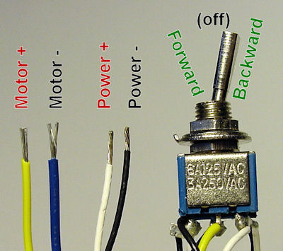
Easiest Way To Reverse Electric Motor Directions Robot Room from www.robotroom.com Click on the image to enlarge, and then save it to your computer by. The top countries of supplier is china, from. 3.1 system structure and wiring. Based on information from seymour duncan here about the switching of the fender jerry donahue tele, this is my wiring diagram. There are no connections between the three gangs in fig 2 intermediate switch related circuit diagrams and wiring diagrams intermediate switch wiring diagram (old cable colours) intermediate switch wiring. Don't disconnect old switch before you are certain about the wiring. Black wires are conventionally used in power circuits and red wire in control circuits for ac magnetic equipment. Connectors position indicator automatic transmission selector.
However his wiring diagram is.
According to the position of its handle, hotness travels on to the next switch on one of the two traveler wires. In the guitar cavity, unsolder the 2 bridge. Here are a few that may be of interest. Guitar pickup & control wiring mods. C4 crankshaft (∗3) position sensor ll. This diagram is a thumbnail. However his wiring diagram is. In position 2 (when the switch is up or 'off'), com and l2 are connected together. 3 way key switch 3 position light switch 3. A wiring diagram is a visual representation of components and wires related to an electrical connection. Most of the links below are also educational. 1a and 1c contact form available. A spst switch only has one throw, but has two positions.