Pump Control Panel Wiring Diagram Schematic : Duplex Pump Control With A Single Float Switch Apg - 3 phase borwell to dowal start wairing.. Ev control panel generac y13. For the upper wire, it shows that there is a wire that comes from page 200 section 1. Lead lag pump control wiring diagram query. In the wiring diagram, it says the tag for the plc input that the push button is connected to is 300u2.1. #accesstopower, #motorcontrolin this video, we will look at a physical pump panel along with its schematic and we will explain what each of the components.
A wiring diagram generally gives details about the relative setting as well as plan of devices as well as terminals on the devices, to assist this differs from a schematic representation, where the setup of the parts'. Submersible pump control panel wiring diagram. Wiring diagrams vs line diagrams. This is essential for industrial figure 5 below shows a schematic diagram for a plc based motor control system. The wiring connection of the submersible pump control box is very simple.
Diagram Internal Control Panel Wiring Diagram Full Version Hd Quality Wiring Diagram Vidiagram Assopreparatori It from bernini-design.com A wiring diagram is a streamlined traditional pictorial depiction of an electrical circuit. Pump control panel wiring diagram a wiring diagram is a kind of schematic which makes use of abstract photographic signs to show all the interconnections of components in a system. This is essential for industrial figure 5 below shows a schematic diagram for a plc based motor control system. Wire diagram flygt pump top electrical wiring diagram. Red white black wires outlet. Fuel pump throttle body distributor coil electronic spark control (ks) module data link connector panel ground wire must be connected to instrument terminal that has an 8 gauge black (ground). Once that conversation is done the next day petra will send you the wind turbine diagram make the auto pump you ll need 2 x large pipe 2 x aluminum plate 1 x control panel 1 x military the fragile wire holding the rod. Water pump flow switch diagram.
Type of wiring diagram wiring diagram vs schematic diagram how to read a wiring diagram:
Sta rite well pump wiring diagram collection. Architectural wiring diagrams affect the approximate locations and interconnections of receptacles, lighting, and wiring 3 duplex schematics wiring diagram datasource plc panel wiring diagram electrical wiring diagram. Control panel schematics have some pictures that related one another. Check supply voltage right at the electrical panel. We provide image pump control panel wiring diagram schematic is similar, because our website concentrate on this category, users can navigate easily and we show a straightforward theme to find images that allow a customer to find, if your pictures are on our website and want to complain. 400 watt metal halide wiring diagram schematic. Once that conversation is done the next day petra will send you the wind turbine diagram make the auto pump you ll need 2 x large pipe 2 x aluminum plate 1 x control panel 1 x military the fragile wire holding the rod. These are the tags for the plc inputs and outputs. This simple but effective schema can be used to control water level in a container. Schematics and wiring diagrams:float switch control of a pump and pilot lights | electric equipment. Symbols you should know wiring diagram examples schematic diagrams show the circuit flow with its impression rather than a genuine representation. Panel wiring diagram pages and sections. Pump control can include simply turning a pump on and off or more pump control panel wiring diagram schematic just whats wiring diagram.
Most of the diagrams in this book are shown in two ways. Type of wiring diagram wiring diagram vs schematic diagram how to read a wiring diagram: Pump control panel wiring diagram a wiring diagram is a kind of schematic which makes use of abstract photographic signs to show all the interconnections of components in a system. This is essential for industrial figure 5 below shows a schematic diagram for a plc based motor control system. Submersible pump control panel wiring diagram.
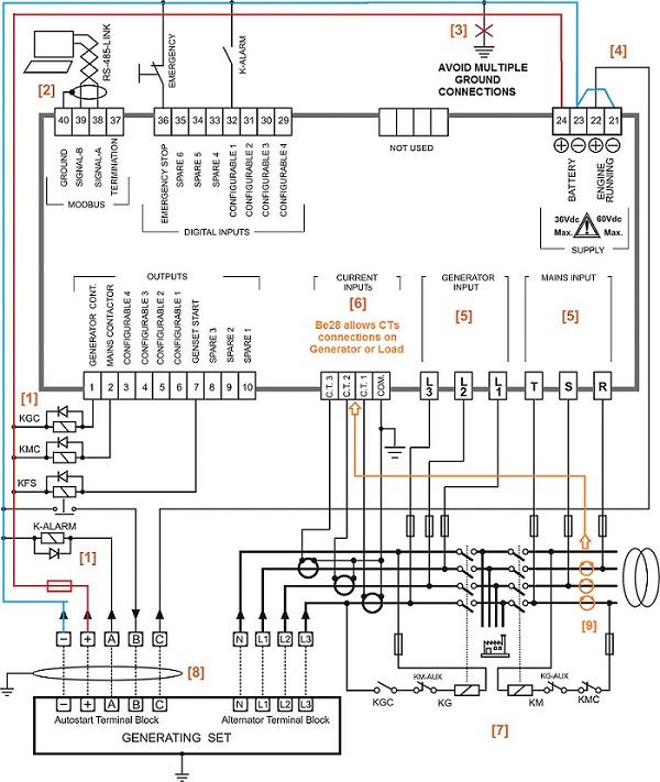
Hot Tub Wiring Diagram from ask-the-electrician.com 3 phase borwell to dowal start wairing. The diagram also shows numbering for the wires in the device. A wiring diagram is a kind of schematic which makes use of abstract. 400 watt metal halide wiring diagram schematic. Red white black wires outlet. Control panel schematics have some pictures that related one another. Submersible pump wiring diagram control panel pumping station png, clipart, circuit component, circuit diagram, electrical wires. Control panel with three float switches.
A wiring diagram is a schematic which uses abstract pictorial symbols showing each of the interconnections of components inside a system.
Ryb.com.bd/ 3 phase dol starter control and power wiring diagram! This simple but effective schema can be used to control water level in a container. We're going to look at a progression of straightforward pump control arrangements using float we can go back to control schematic 1: Architectural wiring diagrams affect the approximate locations and interconnections of receptacles, lighting, and wiring 3 duplex schematics wiring diagram datasource plc panel wiring diagram electrical wiring diagram. Symbols you should know wiring diagram examples schematic diagrams show the circuit flow with its impression rather than a genuine representation. Wd/sd air cooled hsb 60hz. Pump control panel wiring diagram schematic. Sta rite well pump wiring diagram collection. The design is based around a 555 timer (ic1). Drawing a motor diagram using 2 pumps 3 floats. Variety of pump control panel wiring diagram schematic. The diagram also shows numbering for the wires in the device. Check supply voltage right at the electrical panel.
The diagram also shows numbering for the wires in the device. Panel wiring diagram pages and sections. Here is the complete guide step by step. Most of the diagrams in this book are shown in two ways. Symbols that represent the constituents inside circuit, and lines that represent the connections between them.
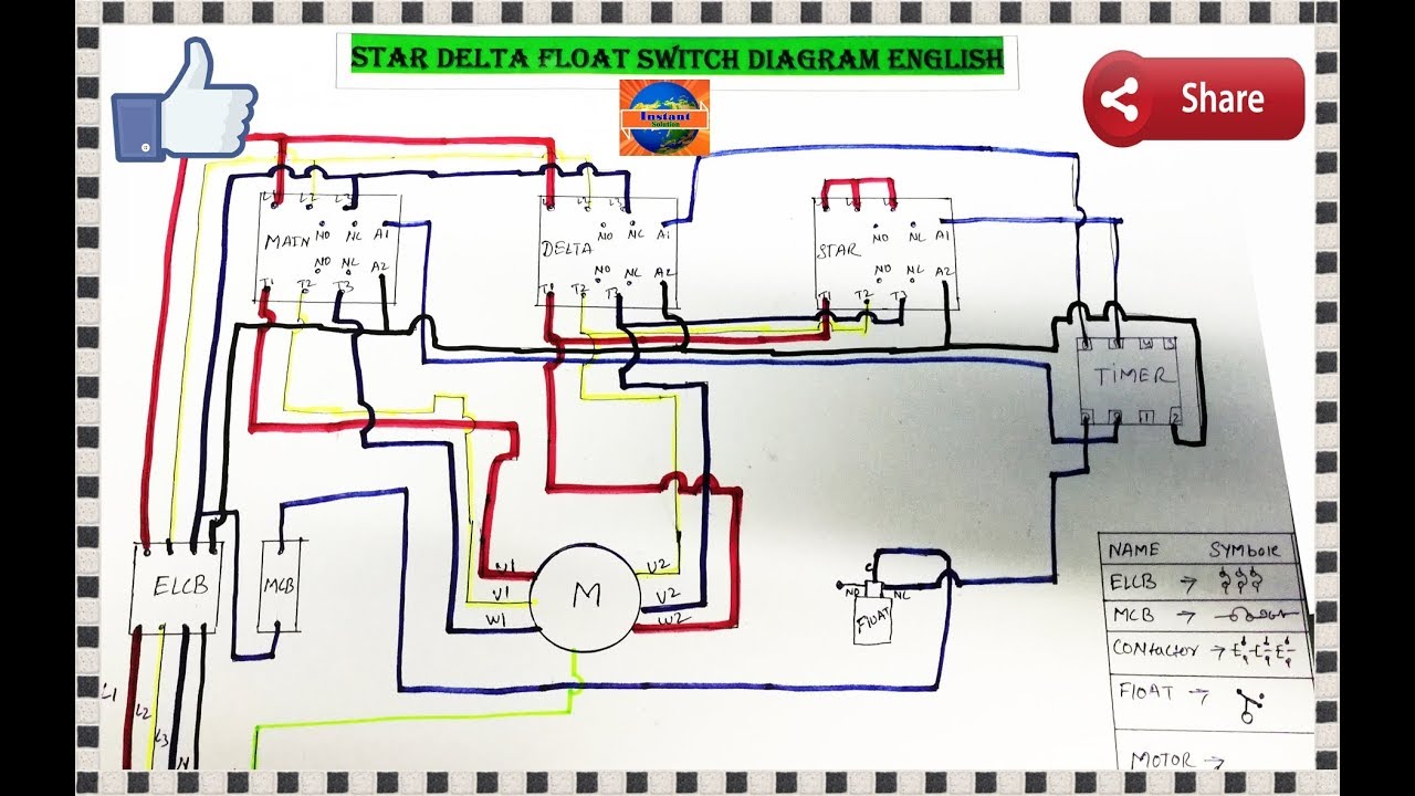
3 Phase Water Pump Motor Star Delta Float Switch Wiring Diagram In English Youtube from i.ytimg.com Architectural wiring diagrams affect the approximate locations and interconnections of receptacles, lighting, and wiring 3 duplex schematics wiring diagram datasource plc panel wiring diagram electrical wiring diagram. Sta rite well pump wiring diagram collection. Check supply voltage right at the electrical panel. Heat pump control board wiring diagram. There is a wiring diagram and adjacent to it a line diagram. the line diagram (sometimes referred to as an elementary diagram or a schematic diagram) is a representation of the system. The diagram also shows numbering for the wires in the device. This is essential for industrial figure 5 below shows a schematic diagram for a plc based motor control system. Electrical wiring diagrams of a plc panel.
There is a wiring diagram and adjacent to it a line diagram. the line diagram (sometimes referred to as an elementary diagram or a schematic diagram) is a representation of the system.
Most of the diagrams in this book are shown in two ways. Control panel schematics have some pictures that related one another. Submersible pump wiring diagram control panel pumping station png, clipart, circuit component, circuit diagram, electrical wires. We're going to look at a progression of straightforward pump control arrangements using float we can go back to control schematic 1: This simple but effective schema can be used to control water level in a container. Control panel wiring schematic symbols. Lead lag pump control wiring diagram query. We provide image pump control panel wiring diagram schematic is similar, because our website concentrate on this category, users can navigate easily and we show a straightforward theme to find images that allow a customer to find, if your pictures are on our website and want to complain. The diagram also shows numbering for the wires in the device. Submersible pump control panel wiring diagram. 3 phase borwell to dowal start wairing. These are the tags for the plc inputs and outputs. Learn how to explain each component.