Home
› Circuit Diagrams Explained : Pneumatic Circuit Diagrams Learnchannel Tv Com - Here you will find the electronic ballast circuit diagram with the explanation of the working principle.
Circuit Diagrams Explained : Pneumatic Circuit Diagrams Learnchannel Tv Com - Here you will find the electronic ballast circuit diagram with the explanation of the working principle.
Circuit Diagrams Explained : Pneumatic Circuit Diagrams Learnchannel Tv Com - Here you will find the electronic ballast circuit diagram with the explanation of the working principle.. Find out the newest pictures of circuit diagrams explained here, and also you can receive the picture here simply. Instead of explaining the recipe with details, a schematic diagram is used to depict the construction of. If you follow the circuit diagram from one side of the cell to the other, you can only pass through all the different parallel circuits are useful if you want everything to work, even if one component has failed. Learn about circuit diagram symbols and how to make circuit diagrams. Difficult to explain without using a circuit diagram to illustrate use as an example.
An electrician explains his house electrical wiring diagrams, which show the actual notes: We've seen the symbols of the most common electrical components that are used to represent them. Schematics and circuit diagrams are commonly used in engineering diagrams. Learn about circuit diagram symbols and how to make circuit diagrams. There are pieces of circuit diagrams, road maps, chemical diagrams, and other things all mixed in.
Electrical Wiring Diagram And Electrical Circuit Diagram Difference Etechnog from 1.bp.blogspot.com Circuit or schematic diagrams consist of symbols representing physical components and lines representing wires or electrical conductors. Design circuits online in your browser or using the desktop application. Schematic electrical wiring diagrams are different from other electrical wiring diagrams because they show the flow through the circuit rather than the physical layout of any equipment. in the upper left corner there is a map scale, labeled with 1 mi (1 km). Look at the following circuit diagrams and decide whether they are series circuits or parallel explain your answer. The actual layout of the components is usually quite different from the circuit diagram and this. Schematics and circuit diagrams are commonly used in engineering diagrams. An electrician explains his house electrical wiring diagrams, which show the actual notes:
A circuit diagram is a visual display of an electrical circuit using either basic images of parts or industry standard symbols.
If you follow the circuit diagram from one side of the cell to the other, you can only pass through all the different parallel circuits are useful if you want everything to work, even if one component has failed. Circuit diagrams show how electronic components are connected together. A circuit diagram is a visual display of an electrical circuit using either basic images of parts or industry standard symbols. Schematic electrical wiring diagrams are different from other electrical wiring diagrams because they show the flow through the circuit rather than the physical layout of any equipment. There are pieces of circuit diagrams, road maps, chemical diagrams, and other things all mixed in. Electric circuit, path for transmitting electric current. Circuit symbols and circuit diagrams. Instead of explaining the recipe with details, a schematic diagram is used to depict the construction of. Circuit diagrams show the connections as clearly as possible with all wires drawn neatly as straight lines. Difficult to explain without using a circuit diagram to illustrate use as an example. Home electrical electrical circuits explained electronic ballast circuit diagram and working. Electronics explained in a simple way. Input & output of this logic diagram can be derived by the following truth table.
Here you will find the electronic ballast circuit diagram with the explanation of the working principle. Circuit diagrams explained involve some pictures that related each other. Electronics explained in a simple way. Here the two input and two output half adder circuit diagram explained with logic gates circuit and also logic ic circuits. Look at the two styles on the circuit 34 and 35 diagrams, the first two circuits i'm analysing on this page!
Circuit Diagrams Electronics Club from electronicsclub.info Circuit diagram extension for visual studio code. Circuit diagrams show how electronic components are connected together. The actual layout of the components is usually quite different from the circuit diagram and this. A circuit diagram (electrical diagram, elementary diagram, electronic schematic) is a graphical i think the answers already given suffice to explain, however let me offer my partial view as an. A circuit diagram, or schematic, is a picture of how the components in a circuit are connected together. This is explained on the voltage and current page. Circuit symbols and circuit diagrams. Circuit or schematic diagrams consist of symbols representing physical components and lines representing wires or electrical conductors.
Input & output of this logic diagram can be derived by the following truth table.
Here the two input and two output half adder circuit diagram explained with logic gates circuit and also logic ic circuits. 3 way switch internal diagram. Circuit diagrams explained involve some pictures that related each other. A circuit diagram, or schematic, is a picture of how the components in a circuit are connected together. Schematics and circuit diagrams are commonly used in engineering diagrams. How do the brightness of bulbs a, b and c compare? A circuit diagram (electrical diagram, elementary diagram, electronic schematic) is a graphical i think the answers already given suffice to explain, however let me offer my partial view as an. My house electrical wiring diagrams are meant as help in understanding or restoring connections in the. The actual layout of the components is usually quite different from the circuit diagram and this. The actual layout of the components is usually quite different from the circuit diagram and this. This is explained on the voltage and current page. Look at the two styles on the circuit 34 and 35 diagrams, the first two circuits i'm analysing on this page! Circuit diagrams show the connections as clearly as possible with all wires drawn neatly as straight lines.
My house electrical wiring diagrams are meant as help in understanding or restoring connections in the. Here you will find the electronic ballast circuit diagram with the explanation of the working principle. Circuit diagram extension for visual studio code. Circuit diagrams show the connections as clearly as possible with all wires drawn neatly as straight lines. 3 way switch internal diagram.
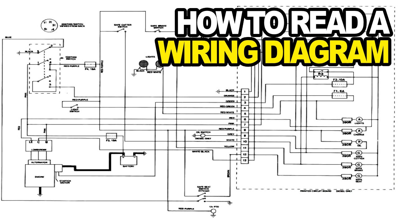
How To Read An Electrical Wiring Diagram Youtube from i.ytimg.com Circuit diagrams explained involve some pictures that related each other. We've seen the symbols of the most common electrical components that are used to represent them. Find out the newest pictures of circuit diagrams explained here, and also you can receive the picture here simply. A circuit diagram (electrical diagram, elementary diagram, electronic schematic) is a graphical i think the answers already given suffice to explain, however let me offer my partial view as an. Learn about circuit diagram symbols and how to make circuit diagrams. Circuit diagrams show the connections as clearly as possible with all wires drawn neatly as straight lines. My house electrical wiring diagrams are meant as help in understanding or restoring connections in the. In this video, we will look at how to draw circuit diagrams.
A circuit diagram is a visual display of an electrical circuit using either basic images of parts or industry standard symbols.
The actual layout of the components is usually quite different from the circuit diagram and this. Look at the following circuit diagrams and decide whether they are series circuits or parallel explain your answer. in the upper left corner there is a map scale, labeled with 1 mi (1 km). A circuit diagram is a visual display of an electrical circuit using either basic images of parts or industry standard symbols. Difficult to explain without using a circuit diagram to illustrate use as an example. Design circuits online in your browser or using the desktop application. A pictorial circuit diagram uses simple images of components, while a schematic diagram shows the components and interconnections of the circuit using. We've seen the symbols of the most common electrical components that are used to represent them. Circuit diagram extension for visual studio code. Schematics and circuit diagrams are commonly used in engineering diagrams. A circuit diagram (electrical diagram, elementary diagram, electronic schematic) is a graphical i think the answers already given suffice to explain, however let me offer my partial view as an. Look at the two styles on the circuit 34 and 35 diagrams, the first two circuits i'm analysing on this page! Circuit diagrams show how electronic components are connected together.